Smart Modify Configuration
While running the Smart Modify tool, a number of configuration options are available to the user, listed below:
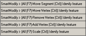
- Smart Modify Configuration Options: When a feature is selected, an additional icon is displayed to indicate the mode Smart Modify is in:
 Move Vertex - displayed when within tolerance of a segment's vertex.
  Move Segment - displayed when within tolerance of a segment without being in tolerance of a segment's vertex.
  Remove Vertex - displayed when the <Ctrl> key is pressed and within tolerance of a segment's vertex.
  Add Vertex - displayed when the <Ctrl> key is pressed and within tolerance of a segment without being in tolerance of a segment's vertex.
  Scale: If within the tolerance of a cell feature, the following icon will be displayed:
The <F7> key toggles in and out of single mode. If in single mode, all related features will be ignored while populating the tree view.
In addition to the icon feedback, the MicroStation prompt will also reflect the different modes and if in single mode or not.
-
Feature Toggle: each feature in the tree view has a toggle that can be used to control if that feature will be moved or not.
- Constrain Angle: For features related to linear features, the user can control the angle by which they move. These feature are identified by an additional icon beside the check box in the tree view.
-
Construction Geometry: It is typical that a layout requires alignment or offset relative some existing feature or geographic geometry. This is accomplished using temporary linear geometries that will be removed when the command exists or restarts.The following key-in can be used to toggle in and out of "Construction Geometry" mode:
xfmstdutiladdin smartmove construct
Once in "Construction Geometry" mode:- Select a location to locate a linear feature.
- Drag the temporary construction geometry to the desired location.
- Use the left mouse click to accept the construction geometry and right click to reject it and look for another feature at that location.
- Repeat to add additional construction geometries.
- Once done, rerun the key-in to exit "Construction Geometry" mode.
 Constrained will maintain the existing angle of the line.
  Not Constrained will maintain the location at which it is connected to its related feature based on a percentage of the related feature's line length.
